FSM for the BLE Embedded App
Foundation
FSMs are used when a system has distinct modes or states and must respond to asynchronous events in a predictable, deterministic way. They make behavior modular, safe, and maintainable, especially when handling concurrent inputs, sequences, or errors.
Finite State Machines A finite state machine is a mathematical model of computation, this sounds scary, arcane even but the underlying concept happens to be very simple. It is a machine or a system that can be in exactly one state out of a fixed number od states.
FSM basics: A state machine can change from one state to another based on some input. such a change is called a transition.
Consider something like an elevator that whose sequence of stops is detemined by the floors requested by rider and these can be added by a rider pressing a button.
FSMs can be divided into acceptors, classifiers, transducers and sequencers.
- Acceptors producea binary output, they run inputs through two states accepting and non accepting and each part of the input can trigger one of the other.
- Classifier are more advanced acceptors that produce outputs that are more than 2 types.
- Transducers produce output based on input and/or state.
Moore Machinethat uses only entry actions and output depends on state.Mealy Machinethat uses input actions and output depends on input and state. - Sequencers are a subclass of acceptors and transducers that have a single letter input and produce only one sequence, this can be an accepter or a transducer output.
Potential events in the BLE system
- BLE connect/disconnect
- New temperature reading available
- New microphone data available
Map the BLE App to a State Machine
The Goal: here is to identify states and transitions for the BLE application.
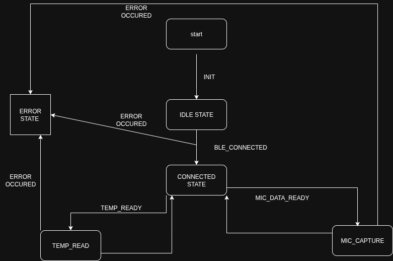
- Step 1: Potential states
IDLE– BLE disconnected, sensors inactiveCONNECTED– BLE connected, sensors idleTEMP_READ– Temperature sensor reading in progressMIC_CAPTURE– Microphone active, capturing audioERROR– Sensor or BLE failure
- Step 2: Identify events
BLE_CONNECTED/BLE_DISCONNECTEDTEMP_READYMIC_DATA_READYERROR_OCCURRED
- Our state transitions
 —
—
Zephyr SMF Implementation Design
While we could go an implement this ourselves as a struct and transitions in our threads, we can leverage the framework that Zephyr provides us. Which is the SMF
Enabled by the CONFIG_SMF option in KConfig.
Here the state is represented by 3 functions. The entry actions, the run actions and the exit actions.
Enty and exit have the prototype
void fun(void *obj);
Whereas the run action has
smf_state_result fun(void *obj);
In order to do this we would need to do the following.
- Define states for each part of your app
- Identify entry and exit actions for each state
- Plan event dispatching for BLE and sensor events
- Consider asynchronous events from BLE notifications or sensor interrupts
Map out order of transitions and entry/exit actions on paper
Advanced FSM Patterns
Handle complexity, concurrency, and real-world edge cases.
Consider the option CONFIG_SMF_ANCESTOR_SUPPORT
- Guard conditions (e.g., only start MIC_CAPTURE if BLE connected)
- Event queuing for fast sensor events
- Hierarchical states (parent
SENSINGstate with child statesTEMP_READ,MIC_CAPTURE,ENV_SENSE) - Error handling (
ERRORstate) - Power management: sleep/idle when BLE disconnected
Review and What we did.
- Steps:
- Draw the final FSM diagram with states, transitions, and events
- Annotate entry/exit actions for each state
- Walk through a sample sequence: BLE connects → TEMP_READ → ENV_SENSE → MIC_CAPTURE → BLE disconnect → IDLE
- Optionally, simulate the FSM on paper to verify logic