Sliding Window Fir For Audio
Sliding Window FIR filter for Audio - Designing the Filter
What are Digital Filters.
Filters are used in DSP extensively perhaps even the most used aspect of DSP. Typically used to separate or restore signals.
e.g
- Removing noise
- combining signals
Inputs to a digital filter will usually be a sequence of numbers, spaced equally in time, this is due to a fixed sampling frequency. So in essence we are collecting amplitudes of a signal at points in time, in order to convert it to a discrete form that our digital computers can comprehend.
We use a filter to apply what is known as a Frequency Response, this is there used to perhaps
remove noise or separate signals. We design this Frequency Response.
Outputs from a digital filter will also usually be a sequence of numbers, usually spaced the same as the input and, with the same number of elements but some filters may drop elements e.g decimation filters.
Designing Our Filter
Ok so that’s how they work, how do we make our own? So in order to come up with a filter we first need to come up with the desired frequency response. I.e how does our filter react to various levels of frequencies.
Once we have this then we can take the inverse of its Fourier Transform
and that gives us the Impulse response.
Window Sinc Method:
Sinc Function
Lets say we have a low pass filter, and we want to pass frequencies below a
certain cutoff frequency and above that we dont, lets say that frequency is 50hz
this btw is out Frequency Response from above i.e pass frequencies below 50hz otherwise
don’t.
Now that we have a frequency response we can apply an inverse Fourier tranform to it so that we obtain our impulse response. The formula for this is.
\[h(t) = \int_{-\infty}^{\infty} H(f) \, \bigl[e^{j 2 \pi f t} \bigr] \, df\]This may look arcane, it is not. What it is saying is we are applying a formula (Inverse Fourier Tranform ) to small values from negative infinity to positive infinity, now we dont need such a large range so instead for our case we will apply the formula to small values from -50 to +50 hz.
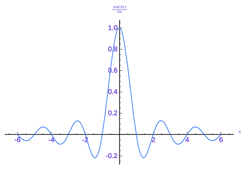
Solving the equation above for our frequency gives the sinc function that looks
as follows when plotted
However this results in some problems
- The response is non-causal which means it depends on some inputs from the future, since we can’t implement that we need to shift it to the right so we end up causal.
- The values are infinite length, and we want a fixed size for our FIR, the answer here is to truncate it.
- The values are still in the time domain which is continous but in this case we want them discretized so we can have them in a discrete domain like frequency.
All this results in a repsonse that looks as below

This still does not fix our issues, since the truncation actually causes us to have high frequency side lobs basically called discontinuties or in audio this would sound like pops or clicks!
Windowing Function
These discontinuties that we just encountered, actually bring us right to the next concept.
A windowing function is a smoothing, what this enables us to do is basically smooth out the side
lobs by multiplying it to the frequency response
And hence we have Windowed FIR filter!
Key Factors when Designing Filters
- Sampling Frequency
- Filter Length, a longer filter is more work but enables us to have a higher resolution.
- Frequency response, low-pass, high-pass, band-pass e.t.c
- Windowing function, Hamming, Hann, Blackman and so on
- Time domain properties so we dont distort the frequency